steel-tapered-haunched-beam-design

Steel Tapered & Haunched Beam Design: Variable Depth & Eaves

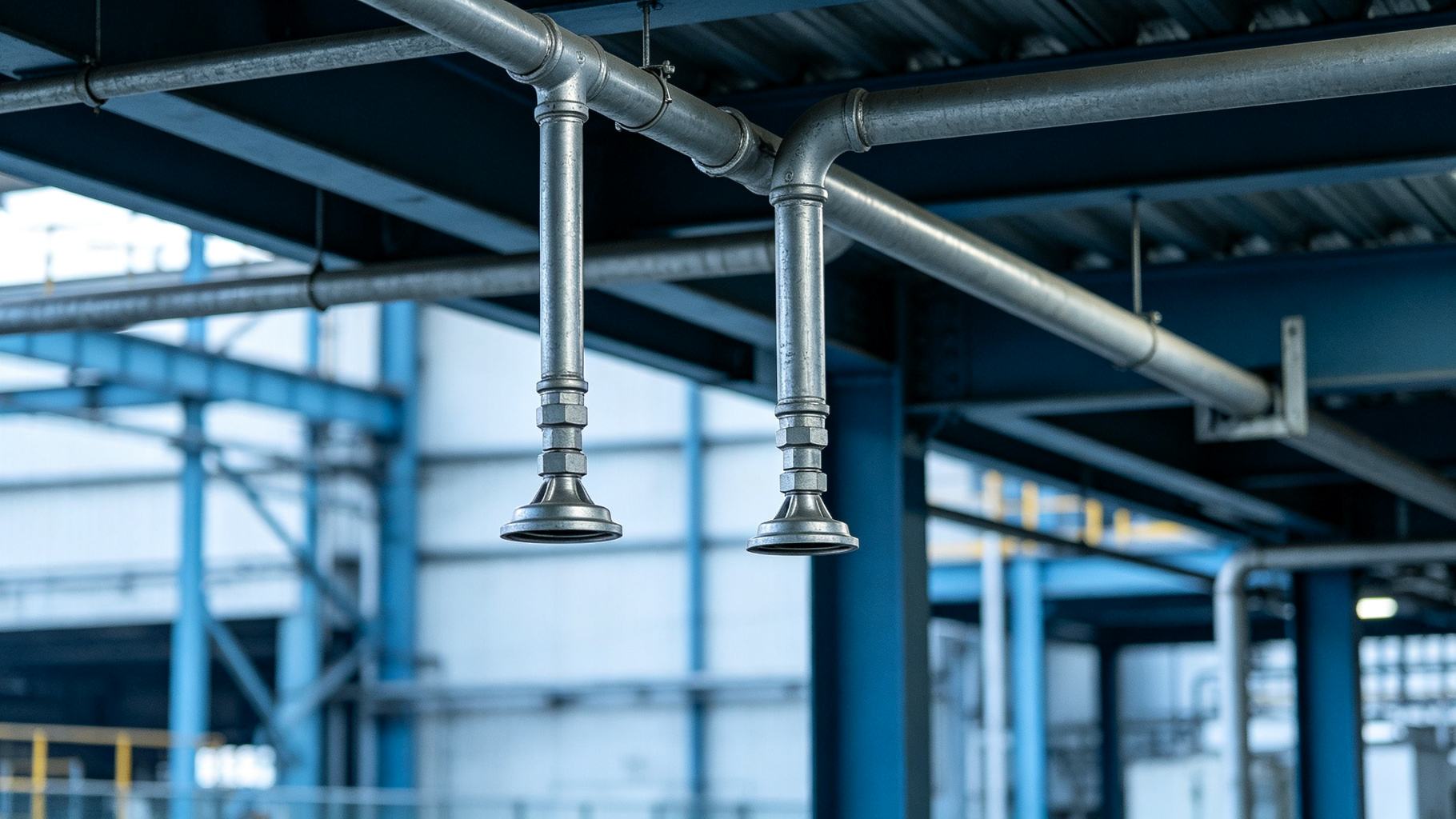
A portal frame rafter whose depth grows linearly from ridge to eaves, where a triangular haunch deepens the column-to-rafter joint to carry the peak negative moment—section and moment envelope tracking each other.
Steel tapered haunched beam design is the art of sizing a member whose depth varies along the span and whose eaves joint carries a deeper haunch—matching section to bending demand for long-span economy. A plate girder is one constant depth welded I-section. A tapered beam is smarter: it gets deeper where the moment is biggest and slims down where it is not, and at the eaves it grows a haunch—all to track the moment envelope with less steel. The controlling questions are: where does the depth change, how steep can the web slope be, how deep should the eaves haunch run, and how do you check stability at every varying-depth section?
This guide walks through the difference between tapered rafters and constant-depth plate girders, the variable-depth section schedule, the eaves haunch moment connection, web slenderness and lateral-torsional buckling at changing depth, and the economic span window where tapered design wins. Our steel plate girder design deep dive covers constant-depth welded sections. This article is about varying depth and eaves haunches.
Tapered/Haunched Beam vs Plate Girder
It helps to set the boundary. A plate girder is a welded I-section whose web height is constant across the span, stiffened by transverse (and sometimes longitudinal) stiffeners; its depth is chosen for the maximum moment and carried all the way to the supports. A castellated beam starts from a constant rolled section and cuts and re-welds the web to introduce openings and increase depth uniformly; see steel castellated beam web opening design for that logic. A composite beam adds a concrete slab and shear studs to work compositely; see steel composite beam design deep dive. None of these vary the raw depth along the span.
A tapered/haunched beam does. Its depth changes continuously (or in steps) from support to midspan, and at the eaves it grows a local deepened knee called the haunch. The whole point is to put steel where the bending moment is high and remove it where the moment is low. This is the core economic logic of steel tapered haunched beam design: section follows moment, not the other way around. For simply supported members, that means deep at midspan and shallow at the ends. For portal frame rafters, it means shallow at the ridge (low moment) and deep at the eaves (high negative moment), with the haunch providing a local depth boost at the column line.
Why this saves steel. A constant-depth beam is sized for the maximum moment and carries that depth to regions where the moment is a fraction of capacity—wasted section. A tapered beam tracks the envelope: the section modulus at any cut equals roughly what the moment at that cut demands. For portal frames, the eaves haunch amplifies the local bending depth without forcing the entire rafter to run at eaves depth. The result is 10–20% less steel than an equivalent constant-depth section in the 24–36 m (80–120 ft) span band. Long-span applications are covered in long span steel structure.
Table 1 — Beam Type Comparison (typical industrial roof, 25–35 m / 80–115 ft span)
| Type | Section | Best Span (m / ft) | Relative Steel Use | Notes |
|---|---|---|---|---|
| Rolled W-shape | Constant depth | 6–12 / 20–40 | 1.00 (baseline) | Economical short spans |
| Plate girder | Constant depth, welded | 20–40 / 65–130 | 1.10–1.25 | Stiffener-heavy |
| Castellated beam | Constant depth, opened web | 12–24 / 40–80 | 0.95–1.05 | Mid-depth only |
| Tapered rafter | Variable depth | 24–36 / 80–120 | 0.80–0.90 | Tracks moment envelope |
| Tapered + haunched | Variable + eaves knee | 24–40 / 80–130 | 0.75–0.85 | Portal frame sweet spot |
| Truss | Built-up chords | 40+ / 130+ | 0.70–0.80 | Beats taper beyond 40 m |
Tapered Beam — Variable Depth Design
Three geometries dominate steel tapered haunched beam design in practice:
- Straight-web tapered rafter. One edge of the web is cut straight on a slope, giving a linearly varying depth. This is the most common portal frame rafter: deep at the eaves, shallow at the ridge.
- Pitched/cambered rafter. The web is folded into a light pitch (typically 1:10 to 1:20 roof slope) with a small camber, used in gable frames where the ridge is a pinned or shallow moment joint.
- Tapered column. The column itself tapers, deep at the base and shallow at the top, matching the cantilever moment diagram of a portal column.
Control sections. You must design at every cut where the section changes materially: the maximum-moment section (midspan or eaves), the minimum-moment section (ridge or column top), and every step point where the slope changes. For each control section, compute the bending strength, shear strength, web slenderness, and deflection contribution. Because the moment of inertia I(x) varies along the member, deflection must be integrated numerically (or segmented) rather than taken from a standard constant-depth table. Serviceability limits are covered in steel structure deflection control.
Web slope limits. Practical web slopes run 1:60 to 1:20 (vertical:horizontal). Steeper slopes (e.g., 1:10) increase fabrication cost, complicate the flange-to-web welding sequence, and raise lateral-torsional buckling risk at the shallow end. The tapered section's lateral-torsional buckling strength cannot be taken from a uniform beam formula; you must use a varying I_y(x) critical moment approach, as covered in steel lateral torsional buckling design. Local plate slenderness at the shallow end also rises, which is addressed in steel member local stability.
Table 2 — Tapered Rafter Section Schedule (illustrative, 30 m / 100 ft span portal rafter, Q355B / A992)
| Location | Depth (mm / in) | Web Slope (V:H) | Factored Moment (kN·m / ft·kip) | Notes |
|---|---|---|---|---|
| Ridge (pinned) | 450 / 18 | 1:40 | 0–150 / 0–110 | Minimum section |
| Quarter point | 700 / 28 | 1:40 | 600 / 440 | Mid-taper |
| Midspan | 850 / 34 | 1:40 | 850 / 625 | Max positive moment |
| Eaves (before haunch) | 700 / 28 | 1:40 | 700 / 515 | Start of haunch |
| Eaves (with haunch) | 1,200 / 48 | Stepped | 1,100 / 810 | Max negative moment |
Haunched Eaves Moment Connection
At the eaves, the portal rafter runs into the column top and the negative moment peaks. The haunch is the local deepened knee that carries that moment. In a typical steel tapered haunched beam design, the haunch:
- Extends 1/10 to 1/8 of the span back from the column centerline (about 3–4 m / 10–13 ft for a 30 m / 100 ft frame).
- Reaches 1.5 to 2× the midspan depth at the column face (e.g., 1,200 mm / 48 in deep when midspan is 800 mm / 32 in).
- Is usually built as a welded T-shape or triangular knee, with the bottom flange thickened and the web locally reinforced.
The haunch raises the section modulus at the joint, which lowers the flange force and panel-zone shear. It also lets the rafter body stay shallow—so the frame does not waste steel running eaves-depth all the way to the ridge. The haunch point itself is a step section; you must check the web slope transition and the flange-to-web weld at that cut. The column-to-rafter joint is a full moment connection, typically shop-welded at the haunch and field-bolted at a splice; connection detailing is covered in steel structure connection design and weld sequencing in steel welding distortion control. The haunched eave joint is the heart of a portal frame; our portal frame steel structure design guide covers how gravity and lateral loads flow through the tapered columns and rafters, and why the eave moment connection governs the whole frame's lateral stability.
Table 3 — Haunch Dimension & Moment Schedule (illustrative portal frames, Q355B / A992)
| Span (m / ft) | Haunch Length (m / ft) | Eaves Depth × Mid Depth (mm / in) | Notes |
|---|---|---|---|
| 18 / 60 | 1.8 / 6 | 800 × 450 / 32 × 18 | Light portal, no crane |
| 24 / 80 | 2.5 / 8 | 1,000 × 600 / 40 × 24 | Typical warehouse |
| 30 / 100 | 3.0 / 10 | 1,200 × 800 / 48 × 32 | Crane-capable frame |
| 36 / 120 | 3.6 / 12 | 1,400 × 950 / 56 × 38 | Heaviest tapered frame |
| 42 / 140 | 4.0 / 13 | 1,600 × 1,100 / 64 × 44 | Truss becomes competitive |
Spanning 20+ m Without Over-Sizing Every Beam?
We taper rafters to the moment envelope, add eaves haunches where the negative moment peaks, and check LTB and web slenderness at every varying-depth section. Tell us your span and roof load.
Web Slenderness, LTB at Varying Depth
The shallow end of a tapered rafter is where stability problems cluster. As depth drops, the web slenderness ratio h/t_w rises (web stays roughly the same thickness, but depth shrinks), so local shear buckling and web crippling risk climb. Meanwhile, the lateral-torsional buckling (LTB) critical moment depends on the weak-axis moment of inertia I_y—which drops fast as depth and flange width reduce. You cannot use a uniform-beam LTB formula; you must integrate the varying I_y(x) and varying moment gradient.
The good news is that roof purlins and roof decking provide continuous lateral support to the top flange. If the rafter top flange is laterally braced at every purlin, L_b is short and LTB is rarely the governing limit state at the shallow ridge section. Purlin systems are covered in steel purlin system. If the rafter bottom flange is unbraced (common in eaves haunches), you need either a lateral strut at the haunch point or a wider flange on the bottom to keep I_y adequate.
In seismic zones, the haunch joint must be detailed for inelastic cyclic demand. The panel zone, the haunch-to-rafter step, and the bolt splice all need capacity-protected design. Seismic requirements are covered in steel structure seismic design deep dive.
Economic Spans & Steel Savings
Where does steel tapered haunched beam design actually pay off? The sweet spot is 24–36 m (80–120 ft) clear spans, typically warehouses, logistics buildings, aircraft hangar bays, and light industrial workshops. In this band, a tapered rafter with eaves haunch uses roughly 10–20% less steel than a constant-depth plate girder doing the same job. The haunch also lets the supporting column be slimmer—the joint is strong even though the column body is not oversized.
Beyond about 40 m (130 ft), trusses, space frames, or cable-supported systems usually beat a tapered beam on steel weight. Below about 18 m (60 ft), a rolled W-shape is cheaper to buy and fabricate than a welded tapered rafter. Tapered design is not universally better; it is best in the middle band where moment gradients are steep and spans are too long for rolled sections but too short for trusses.
Fabrication adds cost: the web must be CNC-cut on a slope, flanges must be cut to length along the taper, and the haunch is a localized welded assembly. But the steel saving usually offsets the extra cutting cost, and the tapered rafter ships as two or three bolt-connected segments—easy to truck and erect. Digital fabrication workflows are covered in steel building bim digital fabrication. Buildings with crane rails also benefit; see overhead crane steel building for how the rafter interacts with runway girders.
Conclusion
Steel tapered haunched beam design is about section-tracking-moment: vary the rafter depth to follow the bending envelope, and deepen the eaves with a haunch where the negative moment peaks. The shallow sections need their own LTB and web-slenderness checks, because a tapered beam is not a constant-depth beam with a sloped edge—it is a family of sections along the span. Get the span, roof slope, and load on the table and we will lay out the rafter and haunch schedule for you. Done right, steel tapered haunched beam design puts steel only where the moment demands it.
About the Author
Senior Structural Engineer
With over 20 years of hands-on experience in steel structure design and prefabricated building engineering, our in-house senior structural engineer has personally contributed to more than 500 steel building projects—including warehouses, industrial factories, aircraft hangars, agricultural buildings, and commercial structures. The focus is on translating design codes such as AISC 360, ASCE 7, and Eurocode 3 into buildable, cost-effective steel solutions that balance structural performance, fabrication efficiency, and total project cost.
Learn more about our engineering team
Case Example
A regional distribution center in central Indiana required a 30 m (100 ft) clear-span warehouse bay totaling 5,200 m² (56,000 sq ft) with a 1:20 roof pitch and no interior columns. The design brief called for minimizing steel weight while keeping the eaves joint capable of carrying peak negative moment. The challenge was that a constant-depth plate girder sized for eaves moment would run at eaves depth all the way to the ridge—wasting steel in the low-moment region. The solution specified straight-web tapered rafters cutting from 1,200 mm (48 in) deep at the eaves to 450 mm (18 in) at the ridge on a 1:40 slope, with a triangular haunch extending 3 m (10 ft) back from the column centerline. The shallow ridge section was checked for web slenderness and LTB using a varying I_y approach, relying on purlin bracing for lateral support. Total primary frame steel came in at 18% lighter than an equivalent constant-depth plate girder, with deflection within L/360. For long-span economics, see long span steel structure.
Frequently Asked Questions
Q1: What is the difference between a tapered beam and a plate girder?
A plate girder keeps a constant welded I-depth across the span, stiffened by transverse stiffeners; a tapered beam varies its depth along the span—deeper at midspan or the eaves where moment is high, slimmer where it is low—to track the moment envelope and save steel.
Q2: What is a haunch at the eaves?
A haunch is a deepened triangular knee at the column-to-rafter joint where the negative moment peaks. It typically runs 1/10–1/8 of the span and reaches 1.5–2× the midspan depth, increasing the joint's bending capacity without over-sizing the entire rafter.
Q3: Is a tapered beam better for long spans?
For 24–36 m (80–120 ft) spans, tapered rafters can save 10–20% steel versus constant-depth sections. Beyond about 40 m (130 ft), trusses or cable systems usually become more economical; below 18 m (60 ft), rolled W-shapes win on simplicity.
Q4: What stability checks vary with depth?
At shallower sections, web slenderness h/t_w and lateral-torsional buckling risk rise. You must check LTB with the varying moment of inertia I_y(x), and rely on purlin/roofing bracing for lateral support at the lighter sections.
Q5: What is a practical web slope for a tapered rafter?
Practical web slopes run 1:60 to 1:20 (vertical:horizontal). Steeper slopes increase fabrication cost, complicate flange-to-web welding, and raise LTB risk at the shallow end. The exact slope should be chosen so that the shallow section still satisfies web-slenderness limits.
Taper to the Moment, Haunch the Eaves—Steel Where It Pays Off.
We size tapered rafters to the bending envelope, deepen eaves with haunches, and check LTB at every varying-depth section. Tell us your span, roof slope, and load.
🏭 Explore: Steel Warehouse · Steel Workshop
Reference Links
- AISC 360 Specification for Structural Steel Buildings — governing US code for strength, stability, and design of tapered and haunched members.
- Metal Building Manufacturers Association (MBMA) — industry standards and design manuals for tapered steel building systems, portal frames, and purlin-braced rafters.
steel-building-energy-audit-net-zero-retrofit
steel-web-crippling-bearing-stiffener-design