steel-overhead-crane-runway-maintenance

Steel Overhead Crane Runway Maintenance: Gauge, Elevation & Wear

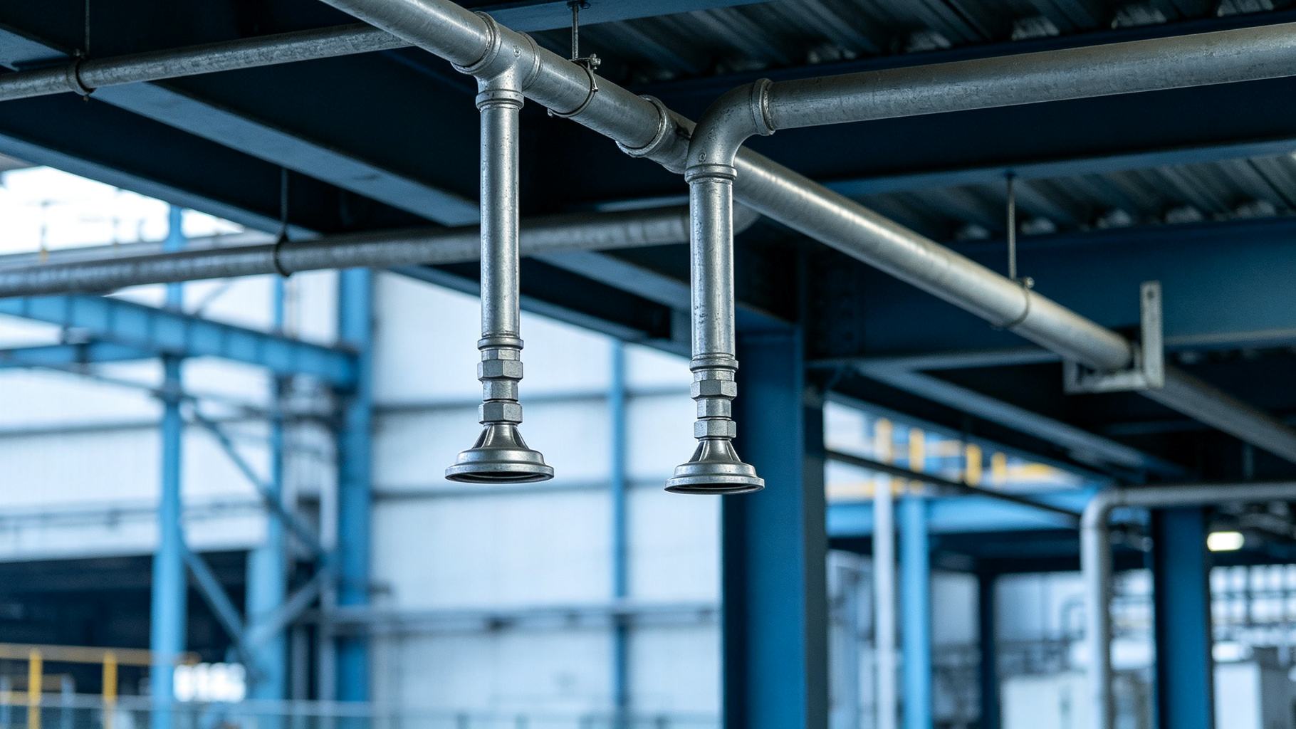
Blue-gray industrial tone—a technician on a maintenance platform inside a steel plant using a laser alignment tool aimed along a crane rail, bolted rail clips and holding bolts clearly visible, the runway girder and column bracket below intact, an overhead crane parked further down the bay, cool industrial lighting, no text in frame.
An overhead crane that weaves and sways 10 m (33 ft) in the air does not just annoy the operator—it pounds the runway beam, fatigues the rail splices, and eventually cracks the column bracket. That damage almost always starts with a rail gauge off by 10 mm (3/8 in) and a deferred annual survey.
This guide covers steel overhead crane runway maintenance: the rails, brackets, clips, and supporting girders that carry every lift. Most runway failures are gradual, measurable, and preventable—they just get ignored until the crane derails. For the design side of the same building—column spacing, crane beam selection, wheel loads—read overhead crane steel building. This piece is what you do after the building is running.
The Runway System — What Wears Out
A crane runway is a moving-load steel structure, not a static roof frame. It deserves a different maintenance rhythm.
Components. The runway system includes the runway girder (the steel beam the rail sits on), the rail itself (QU100 / A100 / P50 sections), rail holding clips and bolts, the end stops and bumpers, and the supporting structure—column brackets, horizontal bracing, and brake trusses.
Common failure modes.
- Gauge spread. Lateral wheel forces plus thermal cycling push the two rails apart over years.
- Elevation drift. Girder camber loss and column settlement make the rail sag.
- Rail head wear. Rolling contact wears the head down at roughly 0.5–2 mm per year depending on duty cycle.
- Low / dipped splice joints. Wheel impact pounds joints unevenly.
- Loose or sheared clip bolts. Vibration undoes torque over months.
- Fatigue cracks in the runway beam. Concentrated wheel loads at stiffener ends.
The maintenance-versus-replacement decision is simple: rail head wear under 10% of original height can be ground and re-profiled; 10–20% is monitored and scheduled; over 20% is replaced immediately. Fatigue cracks trigger a reinforcement or replacement assessment.
For the lifecycle view, see steel building maintenance cost lifecycle; for the fatigue methodology behind crack calls, read steel structure fatigue assessment.
Table 1: Runway System Component & Typical Failure Mode
| Component | Function | Common Failure | Inspection Method | Frequency |
|---|---|---|---|---|
| Crane rail (QU100/A100) | Wheel running surface | Head wear, side wear | Rail wear gauge | Annual |
| Rail holding clips | Fix rail to girder | Loose, sheared bolts | Torque wrench | Quarterly |
| Splice joints | Rail continuity | Vertical / horizontal offset | Straightedge + feeler | Quarterly |
| Runway girder | Support rail | Fatigue crack at stiffener | Visual + MT | Annual |
| Column bracket | Support girder | Cracked weld, settlement | Visual + UT | Annual |
| End stops & bumpers | End-of-travel stop | Cracked weld, degraded rubber | Visual | Monthly |
| Bracing & ties | Lateral stability | Loose connection | Visual + wrench | Quarterly |
Typical inspection scope; frequency tightens for heavy-duty (A6/A7) cranes.
Rail Gauge & Elevation Survey
Two numbers define whether a runway is behaving: rail gauge (distance between rail centerlines) and rail elevation (height of rail top relative to design). Most weaving, wheel wear, and rail spalling traces back to one or both being out of tolerance.
Gauge tolerance. Per CMAA 70, gauge should be within ±5 mm (±3/16 in) of design spacing. Between adjacent columns, the tolerance tightens to ±3 mm (±1/8 in). Over the full building length, cumulative deviation should not exceed ±10 mm (±3/8 in). Measure with a total station or laser tracker; a calibrated tape works for spot checks but not for a full survey.
Elevation tolerance. Rail top elevation should be within ±10 mm (±3/8 in) of design. At the same cross-section, the two rails must not differ by more than 10 mm (3/8 in). Between adjacent columns, the step must stay under 5 mm (±3/16 in). Measure with a level or laser level.
Why it drifts and how to fix it. Gauge spreads because of lateral wheel forces and thermal expansion—correct by shifting clips and re-torquing. Elevation drops from girder camber loss or column settlement—correct by adjusting shim thickness under the rail. Side sway points to loose bracing—re-weld or tighten. All adjustments happen during low-load windows, ideally overnight.
For fatigue design context, see steel structure fatigue design; for coating maintenance on the runway beam, read steel structure corrosion maintenance schedule; for the overall stability the bracing preserves, see steel structure overall stability.
Table 2: Rail Tolerance Limits & Measurement Method
| Parameter | Allowable Deviation (Metric / Imperial) | Measurement Tool | What It Indicates |
|---|---|---|---|
| Rail gauge (overall) | ±5 mm / ±3/16 in | Total station / laser tracker | Lateral spread / wheel force |
| Gauge between columns | ±3 mm / ±1/8 in | Steel tape (calibrated) | Local misalignment |
| Cumulative gauge over full length | ≤10 mm / ±3/8 in | Total station | Longitudinal drift |
| Rail elevation | ±10 mm / ±3/8 in | Auto level / laser level | Girder camber / settlement |
| Cross-level between rails | ≤10 mm / 3/8 in | Digital level at rail | Tilt / differential settlement |
| Step between columns | ≤5 mm / ±3/16 in | String + feeler | Local low joint |
Per CMAA 70; tighter tolerances for high-speed or precision cranes.
Rail Wear & Splice Joint Inspection
Wear and joints are where steel overhead crane runway maintenance spends the most time in service.
Rail head wear. Measure both top and side wear at every column line, once or twice a year, using a dedicated rail wear gauge. The acceptance limits are: head-height reduction no more than 15% (about 15 mm or 5/8 in on a QU100 rail) and side wear no more than 10% of rail head width. Below those limits, grinding restores the rail profile; above, replacement is mandatory because worn rails damage crane wheels and risk derailment.
Splice joints. Rail joints should have a designed gap plus thermal expansion clearance—typically 10–15 mm (3/8–9/16 in). Vertical offset at the joint must be under 1 mm (1/32 in), and horizontal offset under 1 mm. Low ("dipping") joints are the most common wear problem: they are corrected by re-torquing joint bolts, adding shim plates, or re-leveling the support under that column. Welded joints are checked for transverse cracks and ground smooth.
End stops and bumpers. End-stop bolts are torque-checked; rubber or hydraulic bumpers are replaced on age or cracking. The first one or two bays at each end get denser gauge and elevation measurements because wheel impact is highest there.
For corrosion under the clips, see steel structure corrosion inspection; for the bracing that keeps gauge stable, read steel building bracing system; for continuous monitoring options, see steel structure iot monitoring.
Table 3: Rail Wear & Splice Acceptance Limits
| Item | Wear / Limit Threshold | Action When Exceeded | Notes |
|---|---|---|---|
| Rail head height loss | ≤15% (≈15 mm / 5/8 in QU100) | Replace rail | Grind if under limit |
| Rail side wear | ≤10% of head width | Replace / profile | Measure at wheel contact |
| Annual wear rate | 0.5–2 mm / year | Monitor & schedule | Duty-cycle dependent |
| Splice vertical offset | ≤1 mm / 1/32 in | Shim or re-level | Check at every joint |
| Splice horizontal offset | ≤1 mm / 1/32 in | Shift rail | Clip adjustment |
| Splice gap | 10–15 mm / 3/8–9/16 in | Adjust gap | Leave thermal clearance |
| Loose clip bolts | Torque within spec | Re-torque all in section | Spot-check quarterly |
Typical limits per CMAA 74; manufacturer instructions override for specialty rails.
Your Crane Is Weaving — Is the Rail Straight or the Beam Fatigued?
We survey runway rails with laser alignment, measure rail wear at every column line, check splice joint offsets, and report fatigue cracks in the runway beam. You get a measured report, not a guess.
Fasteners, Corrosion & Fatigue
The visible rails are the tip of the problem. The invisible fasteners and beam welds are where steel overhead crane runway maintenance prevents surprise failures.
Clip bolts. Check initial torque quarterly and re-torque annually. Typical values are about 80 N·m (59 ft-lb) for M16 clips and 160 N·m (118 ft-lb) for M20 clips, per AISC RCSC specifications. If more than 10% of clips in a section are loose, re-torque the whole section. Bolts with over 30% rust are replaced.
Runway beam fatigue. Concentrated wheel loads cycle the girder millions of times. The high-risk spots are beam-end stiffeners, bottom-flange splice welds, and bracket connections. Magnetic particle testing (MT) is done annually on these welds. Paint that has suddenly cracked or spalled is a visible warning—under it, a fatigue crack is propagating. When a crack is found, reduce the lift load immediately and order an assessment.
Coating. The underside of the rail and the inside of clip angles collect moisture and corrode faster than the rest of the building. Touch up on the same cycle as the rest of the plant: blast to Sa2.5, epoxy zinc-rich primer, polyurethane finish.
For the floor system below the crane, see steel building floor system; for the corrosion program, read corrosion protection.
Maintenance Schedule & Commissioning Check
A practical steel overhead crane runway maintenance program is layered by frequency:
- Daily — operator visual: strange noises, sway, oil leaks, rail surface debris.
- Monthly — clip bolt spot check, rail surface cleaning, end-stop visual.
- Quarterly — rail gauge spot check, splice joint visual, bumper condition.
- Annually — full gauge and elevation survey, rail wear measurement, MT spot-test of critical welds.
- Major overhaul (every 5 years) — rail replacement, girder reinforcement, bracing refurbishment, depending on duty cycle.
After a new crane installation or a major runway overhaul, run no-load, rated-load, and side-load tests, re-survey gauge and elevation, and confirm brake travel and limit switches before normal duty resumes. Document everything as an acceptance report.
Indicative annual maintenance cost: routine inspection USD 1,500–USD 4,000; rail replacement USD 80–150 per m (USD 24–46 per ft); girder reinforcement scoped separately. For the site acceptance protocol, see steel building site acceptance inspection; for lifecycle cost view, read steel building maintenance cost lifecycle.
Conclusion
Steel overhead crane runway maintenance boils down to five numbers: rail gauge within ±5 mm, elevation within ±10 mm, rail head wear under 15%, splice offsets under 1 mm, and clip bolts at design torque. An annual full survey is the minimum; daily operator observation catches the acute failures. Runway beams are moving-load structures—they wear out faster than any roof frame in the same building, and fatigue cracks at stiffener ends must never be ignored.
Straight Rails, Tight Bolts, Quiet Crane — That Is a Well-Maintained Runway.
We survey crane rails with laser alignment, measure wear at every column, check splice offsets, and report fatigue cracks in the runway beam. You get a measured report, not a guess.
🏭 Explore: Steel Factory · Steel Workshop
About the Author
Senior Structural Engineer
With over 20 years of hands-on experience in steel structure design and prefabricated building engineering, our in-house senior structural engineer has personally contributed to more than 500 steel building projects—including warehouses, industrial factories, aircraft hangars, agricultural buildings, and commercial structures. The focus is on translating design codes such as AISC 360, ASCE 7, and Eurocode 3 into buildable, cost-effective steel solutions that balance structural performance, fabrication efficiency, and total project cost.
Learn more about our engineering team
Case Example
A 12-year-old production bay shows what deferred runway surveys do to a crane. The installation was an 80 m (260 ft) runway carrying two 5 t (5.5 USt) bridge cranes on QU100 rail, in an anonymized northern China heavy-industry park. The operator reported weaving wheels and dipping joints. A laser survey found gauge spread of +14 mm against a ±5 mm tolerance, three low splice joints, and rail head wear at about 12%. The correction was overnight: shift and re-torque clips, shim the dipped joints, and re-profile the worn rail head. Magnetic-particle testing of beam-end stiffeners found no active fatigue cracks. After the work, cumulative gauge held within ±5 mm and wheel replacement intervals extended by an estimated 25%. The design baseline is in overhead crane steel building; the crack-call methodology is in steel structure fatigue assessment.
Frequently Asked Questions
Q1: How often should crane rails be inspected?
Daily, the operator does a visual check for strange noises, sway, and oil leaks. Quarterly, spot-check clip bolt torque and clean the rail surface. Annually, run a full gauge and elevation survey, measure rail wear, and magnetic-particle-test critical welds. A major overhaul—rail replacement or beam reinforcement—is typically due every 5 years depending on duty cycle.
Q2: What rail gauge tolerance is acceptable?
Per CMAA 70, rail gauge should be within ±5 mm (±3/16 in) of design spacing. Between adjacent columns, the tolerance tightens to ±3 mm (±1/8 in). Over the full building length, cumulative deviation should not exceed ±10 mm (±3/8 in).
Q3: How much rail wear is too much?
The limit is typically 15% reduction in rail head height (about 15 mm or 5/8 in for a QU100 rail) and 10% side wear. Below these limits, surface grinding restores the rail. Beyond 15%, the rail must be replaced—continued use accelerates wheel damage and risks derailment.
Q4: What causes low spots at rail joints?
Low joints (dipping under the wheel) are usually caused by loose joint bolts allowing vertical movement, insufficient rail support at the splice, or foundation settlement under that column. They are corrected by tightening bolts, adding shim plates under the rail, or adjusting the support elevation.
Q5: How do you detect fatigue cracks in crane runway beams?
Focus inspection on beam-end stiffeners, bottom-flange splice welds, and bracket connections—these see the highest cyclic stress. Use magnetic particle testing (MT) annually on welds, and look for painted surfaces that are suddenly cracked or spalling, which is a visible warning sign of an active fatigue crack.
Reference Links
- CMAA 70 — Specifications for Top Running Bridge & Gantry Cranes — rail gauge, elevation, and wear tolerance standards used in this guide.
- AISC Design Guide 7 — Industrial Buildings: Roofs to Column Anchors — runway beam and bracket design / maintenance reference.
steel-indoor-cannabis-cultivation-facility
steel-building-deconstruction-circular-economy