steel-moment-connection-semi-rigid-design
Steel Moment Connection & Semi-Rigid Design: Stiffness & M-θ
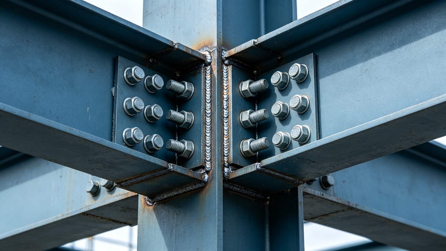
 Close-up of a steel beam-to-column moment connection: silver H-shaped column welded to a wide-flange beam, full-penetration flange welds visible at the top and bottom flanges, high-strength bolts through a web shear plate, engineering drawings laid out beside the joint, and a blurred steel frame workshop in the background.
Steel moment connection semi rigid design starts with an uncomfortable truth: designers often label a connection "rigid" or "pinned" by instinct. In reality every beam-to-column joint sits somewhere on a continuous stiffness curve: it rotates a little under moment, and that rotation changes how the whole frame bends. The discipline classifies joints by rotational stiffness—full-restraint (rigid), simple (pinned), and semi-rigid—and uses the moment-rotation (M-θ) curve to decide how much moment actually reaches the column. Get the classification wrong and the frame analysis lies: beams bend more than expected, columns sway more than expected, and deflections open up.
This article covers the stiffness classification that drives modern joint practice: the three joint classes, the M-θ curve and rotational stiffness, rigid moment connection details, semi-rigid end-plate and angle details, and the effect on second-order frame analysis. Our general steel structure connection design guide covers bolt and weld capacity; this one is about how stiff the joint is and what that does to the frame.
Rigid vs Semi-Rigid vs Pinned — Stiffness Classification
Every beam-to-column connection transfers some combination of shear, axial force, and moment. The useful classification for steel moment connection semi rigid design is by how much moment the joint transfers relative to an ideally rigid joint.
A simple (pinned) connection transfers shear only and is assumed not to transfer moment at all; the beam end rotates freely. A rigid (full-restraint, FR) connection holds the beam end fixed so beam-end moment is distributed into the column as in a moment frame. A semi-rigid connection sits between the two: it rotates under moment and transfers a fraction of the ideal rigid end moment. AISC 360 groups these into Type FR (rigid), Type PR (partially restrained, which includes semi-rigid), and Type simple shear.
The classification changes the whole frame model. This is the core decision in steel moment connection semi rigid design: a pinned frame has to be braced because the beams act as simply supported. A rigid frame can stand unbraced as a moment frame, with beams designed for negative end moment. A semi-rigid frame needs a modified second-order analysis because the joint flexibility softens the effective beam stiffness. Bolt and weld capacity for these details is covered in steel high strength bolt connection deep dive and bolted vs welded connection.
Connection Stiffness Classification
| Type | AISC Class | Moment Transfer | Relative Stiffness | Frame Type | Notes |
|---|---|---|---|---|---|
| Simple / pinned | Type PR (shear) | Shear only | Near zero | Braced frame | Web angle / shear tab |
| Semi-rigid | Type PR | Partial moment | Intermediate | Modified moment frame | End plate, top-seat angle |
| Rigid / FR | Type FR | Full beam-end moment | Near infinite | Moment frame / SMRF | Welded or bolted rigid |
Classification follows AISC 360; the actual M-θ curve decides where a detail falls on the spectrum.
Moment-Rotation (M-θ) Curve & Rotational Stiffness
The language of steel moment connection semi rigid design is the moment-rotation (M-θ) curve. Apply a moment M to a joint and it rotates by θ; the secant rotational stiffness is K_θ = M / θ at the design point, and the initial elastic stiffness K_i is the slope at the origin.
A typical rigid welded joint starts very stiff—K_i high—and stays nearly linear well into the elastic range. A typical semi-rigid end plate starts stiff but softens as the end plate bends and the bolts elongate, often degrading sharply after 0.5–0.7 M_n. A top-and-seat angle starts more flexible from the outset. Designers model these curves with empirical forms: the power (Richard-Abbas) model, a tri-linear idealization, or the Frye-Morris polynomial.
A practical rule of thumb (used in AISC and Eurocode 3 guidance) classifies the joint by normalized stiffness. When K_θ · L_beam / (E · I_beam) ≥ about 20, the joint can be treated as rigid. When it is below about 2, it behaves as pinned. Between those limits, the joint is semi-rigid and must be modeled with its actual M-θ curve. That stiffness data comes from physical testing or from a standard component model—never from a guess. Second-order analysis logic is covered in steel structure second order analysis, and overall frame stability in steel structure overall stability.
Typical Joint Rotational Stiffness Ranges
| Joint Detail | Initial K_i (kN·m / rad) | Moment Capacity (kN·m / ft·lb) | Classification | Notes |
|---|---|---|---|---|
| Web shear tab / web angle | 500–3,000 | 0–15 / 0–11,000 | Pinned | Shear only |
| Top-and-seat angle | 5,000–20,000 | 30–120 / 22,000–88,000 | Semi-rigid | Classic detail |
| Extended end plate (4 bolts) | 20,000–80,000 | 100–400 / 74,000–295,000 | Semi-rigid to rigid | Bolted field erection |
| Flange-welded, web-bolted (WR) | 80,000–200,000+ | 200–800 / 148,000–590,000 | Rigid / FR | Moment frame staple |
| Full-penetration groove weld | 100,000–300,000+ | 300–1,000 / 221,000–738,000 | Rigid / FR | Maximum stiffness |
Stiffness ranges are typical for wide-flange members; obtain certified M-θ data from the connection designer or component model.
Rigid (Full-Restraint) Moment Connections
Rigid connections are the workhorses of unbraced moment frames. The most common detail is the welded-flange, bolted-web (WR) joint: the beam flanges are complete-joint-penetration groove welded to the column flange, and the web is bolted through a shear tab. This detail delivers the high stiffness and ductility expected of a moment frame.
All-welded joints use CJP groove welds at the flanges plus double-sided fillet welds at the web. All-bolted rigid joints use T-stub or extended end-plate details that bolt up in the field. Whichever detail is used, the joint must satisfy strong-column weak-beam proportioning and a panel-zone shear check, so the beam yields before the column or the connection fractures.
Typical SMRF panel-zone doubler plates run 6–12 mm (1/4–1/2 in) thick, and CJP flange welds require a 25–38 mm (1–1.5 in) wide access hole behind the weld for back-gouging. Cyclic qualification typically demands a plastic rotation capacity of at least 0.03 rad (about 1.7°) at the beam end before fracture, and a maximum panel-zone shear strain of 0.004 rad (0.23°) at the design-basis earthquake.
In moderate and high seismic zones, special moment frames (SMRF) per AISC 341 require ductile details: access holes behind flange welds, panel-zone doubler plates, and lateral bracing at beam ends. Those details are often validated by cyclic qualification testing. Stability design logic is in steel structure stability design, seismic detailing in steel structure seismic design deep dive, and column base logic in steel column base plate design.
Rigid Moment Connection Types
| Detail | Weld / Bolt | Use Case | Seismic | Notes |
|---|---|---|---|---|
| CJP flange + fillet web weld | All-welded | Moment frame | OMF / SMRF possible | Highest stiffness |
| Welded flange + bolted web (WR) | Mixed | Most common moment frame | OMF, SMRF when qualified | Field-friendly |
| Extended end plate | All-bolted | Bolted moment frame | OMF possible | Semi-rigid to rigid |
| T-stub flange plate | All-bolted | Bolted moment frame | OMF | Factory bolting |
| SMRF ductile detail | CJP + doubler + bracing | High seismic | SMRF | Cyclic tested |
Seismic classification follows AISC 341; SMRF details require cyclic qualification.
The axial-only cousin of the rigid moment joint is not an end plate but a flat gusset that transfers web-member forces to truss chords. Our truss gusset plate Whitmore and block shear design guide covers the 30-degree effective-width spread, the block shear tear-out check along the bolt line, and the 10–25 mm plate thickness band that keeps the joint elastic at factored member force.
Unsure Whether Your Beam Ends Are Rigid, Pinned, or Semi-Rigid?
We classify joints by M-θ stiffness, size rigid moment connections for SMRF if needed, and feed semi-rigid stiffness back into second-order frame analysis. Tell us your frame type and joint detail.
Semi-Rigid Connections — End Plates & Angles
Semi-rigid practice centers on two details: the extended end plate and the top-and-seat angle. The extended end plate is a plate welded to the beam end and bolted to the column flange with rows of high-strength bolts above and below the beam flanges. It is stiff enough to carry real moment, bolts up in the field, and is the workhorse of semi-rigid frames.
The top-and-seat angle is a more flexible detail: an angle under the beam bottom flange and a smaller angle on top, bolted to the column. It transfers a modest fraction of beam-end moment. A web angle or shear tab alone is essentially pinned.
Extended end plates commonly use 20–40 mm (3/4–1.5 in) thick plate with M20–M30 (3/4–1-1/8 in) high-strength bolts arranged in two to four rows above and below the beam flanges; top-and-seat angles typically run L100×100×10 mm to L150×150×15 mm (L4×4×3/8 to L6×6×5/8). Initial end-plate bolt pretension lands at 155–300 kN (35–67 kip) per bolt depending on diameter and grade.
The benefit of designing semi-rigid is real: the joint absorbs part of the beam-end negative moment, which reduces midspan positive moment and lets you use a smaller beam. This is the central economic argument of steel moment connection semi rigid design. The cost is equally real: the joint rotation increases frame sidesway, so the P-Δ second-order effect grows and must be checked with the actual joint stiffness. Semi-rigid design is also less familiar to reviewers, so the design package must clearly document the M-θ model. Cast steel alternatives are covered in steel cast steel node design, composite beam logic in steel composite beam design deep dive, and lateral bracing in steel lateral torsional buckling design.
How Joint Stiffness Changes Frame Analysis
The reason steel moment connection semi rigid design matters is that the joint stiffness feeds back into the frame. If you model a connection as pinned but it is actually semi-rigid, you overestimate midspan positive moment because the real joint is already carrying some negative moment. If you model it as fully rigid but it is actually semi-rigid, you overestimate column moment because the flexible joint lets the beam end rotate.
The sidesway effect is equally important. Semi-rigid joints soften the effective beam-to-column stiffness, which increases frame drift and amplifies P-Δ effects. A frame that looks OK as a rigid moment frame can drift too much when the real joint flexibility is fed in, and drift-based serviceability limits (typically height/400 to height/500) can become the governing check rather than strength.
Typical unbraced beam spans for semi-rigid moment frames land at 6–12 m (20–40 ft), with span-to-depth ratios of L/d ≈ 15–22. Going beyond L/d = 22 usually forces a switch to rigid (FR) detailing or deeper W-shapes (for example W24–W36, equivalent to 610–915 mm deep sections) to hold drift within serviceability. The added joint flexibility typically reduces effective beam stiffness by 15–35% compared with a fully rigid assumption.
Practical advice: for ordinary industrial buildings, use simple pinned beams with a braced frame—it is simple, robust, and well understood by fabricators, erectors, and building officials. Reserve moment frames and semi-rigid design for unbraced or long-span frames where the lateral load path really demands it, such as open-plan offices with no bracing allowed, retail boxes with clear frontage, or industrial buildings where crane and rack loads preclude a braced bay. Always get the joint M-θ data from testing or a component model; do not assume. A joint that looks rigid on paper but is actually semi-flexible will drift more than the analysis predicted, and a joint that looks pinned but actually carries moment will have unanticipated residual stresses. Second-order analysis logic is in steel structure second order analysis, bracing systems in steel building bracing system, and deflection limits in steel structure deflection control.
Conclusion
Steel moment connection semi rigid design classifies joints by rotational stiffness—rigid, semi-rigid, pinned—and uses the M-θ curve to decide how much moment reaches the column. Semi-rigid is not "approximately rigid"; it requires a proper second-order analysis with the actual joint stiffness. In seismic zones, SMRF-qualified rigid details are the safe choice. Tell us your frame type and joint detail, and our engineers will classify the stiffness, size the moment connections, and feed real joint M-θ data back into the frame analysis.
Rigid, Pinned, or Semi-Rigid? Your Frame Acts on the Answer.
We classify joints by M-θ stiffness, size SMRF details where seismic demands require it, and feed real semi-rigid stiffness into second-order analysis. Tell us your frame type and joint detail.
🏭 Explore: Steel Factory · Steel Workshop
About the Author
Senior Structural Engineer
With over 20 years of hands-on experience in steel structure design and prefabricated building engineering, our in-house senior structural engineer has personally contributed to more than 500 steel building projects—including warehouses, industrial factories, aircraft hangars, agricultural buildings, and commercial structures. The focus is on translating design codes such as AISC 360, ASCE 7, and Eurocode 3 into buildable, cost-effective steel solutions that balance structural performance, fabrication efficiency, and total project cost.
Learn more about our engineering team
Case Example
A two-story 4,800 m² (51,700 sq ft) light industrial and office building in central Texas required an unbraced steel frame with no interior bracing allowed on the ground-floor showroom level. The design team initially modeled all beam-to-column joints as rigid full-restraint connections, which produced overly heavy columns and conservative drift results. The challenge was that extended end-plate connections, while commonly detailed as "moment," actually sit in the semi-rigid range with initial rotational stiffness around 45,000 kN·m/rad. The solution reclassified 24 of 36 perimeter joints as semi-rigid using component-method M-θ curves from AISC Design Guide 4, then ran a modified second-order P-Δ analysis with the actual joint stiffness. Frame drift increased from H/520 to H/410 but remained within the serviceability limit, while beam sizes reduced by one section weight across the frame—saving approximately 8% on total steel tonnage. For second-order analysis methodology, see steel structure second order analysis.
Frequently Asked Questions
Q1: What is the difference between rigid, pinned, and semi-rigid connections?
A pinned (simple) connection transfers shear only and rotates freely. A rigid (full-restraint) connection holds beam ends fixed and distributes frame moment into the columns. A semi-rigid connection sits between the two, transferring a portion of the beam-end moment defined by its moment-rotation (M-θ) curve.
Q2: How do you decide if a joint can be treated as rigid?
Use normalized stiffness: when K_θ · L / (E · I) ≥ about 20 the joint can be treated as rigid; below about 2 it behaves as pinned; between those limits it is semi-rigid and must be modeled with its actual M-θ curve.
Q3: Do semi-rigid connections save steel?
They can. The joint absorbs part of the beam-end negative moment, reducing midspan moment and beam size. The trade-off is increased frame sidesway, which must be checked with second-order (P-Δ) analysis using real joint stiffness data.
Q4: What moment connections are required in seismic zones?
In moderate-to-high seismic zones, special moment frames (SMRF) per AISC 341 require ductile details—complete-joint-penetration welds with access holes, panel-zone reinforcement, and lateral bracing—often validated by cyclic qualification testing.
Q5: Where does the M-θ stiffness data come from?
Joint rotational stiffness must come from physical testing of the detail or from a standard component model (such as the AISC / Eurocode component method) that sums the stiffnesses of the flange, web, bolts, and welds. It should not be guessed.
Reference Links
- AISC 360 Specification for Structural Steel Buildings — stiffness classification, moment frame, and connection design rules.
- AISC Design Guide 4: Extended End-Plate Moment Connections — reference for semi-rigid end-plate design and M-θ behavior.
steel-web-crippling-bearing-stiffener-design
steel-film-studio-soundstage-building